Modbus
Modbus - Documentation
Common
The controller exposes a Modbus ‘Master’ at the specified TCP interface on port 502.
There are dedicated registers for the VFD, PIDs and internal values.
System Registers
| Name | Component ID | Address | RW | Function Code | Value | Register Description |
|---|---|---|---|---|---|---|
| System | 1 | 9 | -W | 0x6 | 1 | Print Modbus Queue |
| System | 1 | 9 | -W | 0x6 | 2 | Print Component Modbus Registers |
| System | 1 | 100 | -W | 0x6 | 1 | Reset Controller |
| System | 1 | 19 | -W | 0x6 | 1 | Print PID controller states |
Remarks
- Implementation for these calls : short ModbusBridge::loop() ./ModbusBridge.cpp
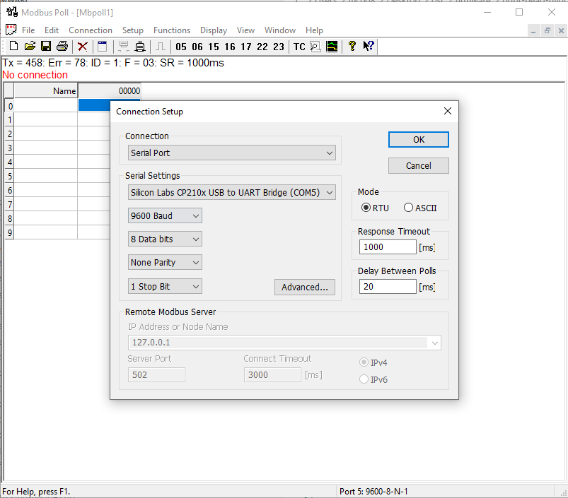
- It requires a USB cable connected, with 19200 bauds, 8 bits, no parity and 1 stop bit. You can use Arduino’s ‘Serial Monitor’ to see the output.
VFD Registers
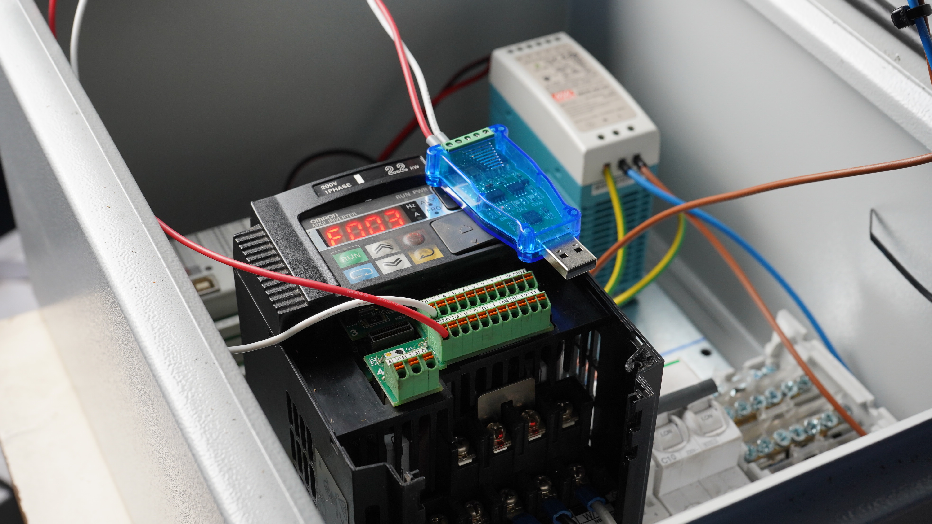
The VFD (Omron - MX2) is being polled and controlled via RS485 at a defined Modbus slave address (Default 1). See more about the setup here.
| Name | Component ID | Address | RW | Function Code | Value | Register Description |
|---|---|---|---|---|---|---|
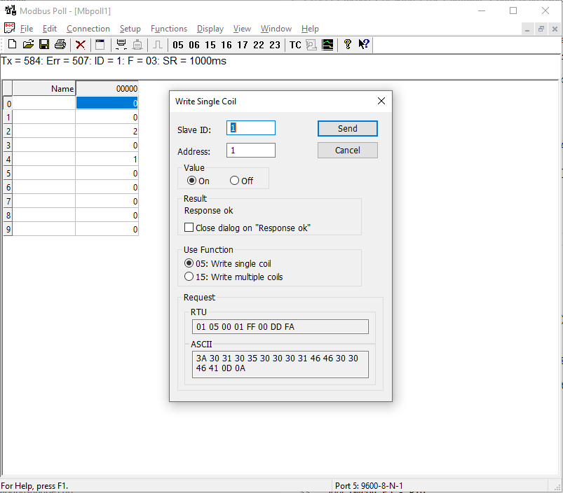
| VFD | 200 | 5 | -W | 0x6 | 1 | Set VFD in RUN mode |
| VFD | 200 | 5 | -W | 0x6 | 2 | Set VFD in STOP mode |
| VFD | 200 | 5 | -W | 0x6 | 3 | Set VFD in RETRACT mode (stop and retract) |
| VFD | 200 | 6 | -W | 0x6 | 0-100 | VFD Target Frequency |
| VFD | 200 | 2 | -R | 0x6 | 0-100 | VFD Current Monitor |
| VFD | 200 | 3 | -R | 0x6 | - | VFD Status OMRON_STATUS_STOPPED=2 OMRON_STATUS_RUNNING=0 |
| VFD | 200 | 4 | -R | 0x6 | - | VFD State OMRON_STATE_ACCELERATING=4OMRON_STATE_DECELERATING=2 OMRON_STATE_RUNNING=3 OMRON_STATE_STOPPED=1 OMRON_STATE_ERROR=8 |
PID Registers
The PID controllers (Omron - EDC5) are being polled and controlled via RS485 at a defined Modbus slave address, starting by default from 4.
| Name | Component ID | Address | RW | Function Code | Value | Register Description |
|---|---|---|---|---|---|---|
| PID | 100 | 20 | R- | 0x6 | 0-Maximum Temperature (PV) |
PID-0 Temperature |
| PID | 100 | 21 | R- | 0x6 | 0-Maximum Temperature / Set Point | PID-0 Set Point (SP) |
| PID | 100 | 22 | R- | 0x6 | Status | PID-0-Status / Default State : ‘Is Heating’ |
| PID | 100 | 23 | R- | 0x6 | 0-Maximum Temperature (PV) |
PID-1 Temperature |
| PID | 100 | 24 | R- | 0x6 | 0-Maximum Temperature / Set Point | PID-1 Set Point (SP) |
| PID | 100 | 25 | R- | 0x6 | Status | PID-1-Status / Default State : ‘Is Heating’ |
Auxillary Registers (Sensors / Switches)
| Name | ID | Address | RW | Function Code | Number Addresses | Register Description |
|---|---|---|---|---|---|---|
| OmronPID | 100 | 20 | R- | 0x6 | 6 | |
| MB_Relay | 300 | 41 | RW | 1 | 1 | |
| MB_Relay | 301 | 42 | RW | 1 | 1 | |
| POT | 400 | 51 | R- | 3 | 1 | |
| POT | 401 | 52 | R- | 3 | 1 | |
| Pos3Analog | 501 | 61 | R- | 3 | 1 | - Read Position : Address=61(3D) -> [Up:1 Middle:0 Down:2] |
| Pos3Analog | 502 | 62 | R- | 3 | 1 | - Read Position : Address=62(3E) -> [Up:1 Middle:0 Down:2] |
| VFD | 200 | 5 | – | 3 | 1 | |
| Stepper | 601 | 70 | RW | -1 | 4 | |
| MotorLoad | 210 | 2 | R- | 3 | 1 | |
| Status - LED | 701 | 84 | RW | 3 | 1 | |
| Status - LED | 702 | 85 | RW | 3 | 1 |
Stepper
| Name | ID | Address | RW | Function Code | Value | Register Description |
|---|---|---|---|---|---|---|
| Stepper-0 | 601 | 70 | RW | 0x6 | 0-5000 | Stepper-Speed |
| Stepper-0 | 601 | 71 | RW | 0x6 | 0-1 | Stepper-Direction |
| Stepper-0 | 601 | 72 | R- | 0x6 | - | Stepper-Status |
| Stepper-0 | 601 | 72 | – | 0x6 | - | Stepper-User |
Feed - Servo
| Name | ID | Address | RW | Function Code | Value | Register Description |
|---|---|---|---|---|---|---|
| Feed - VFD - Ratio | 601 | 16 | -W | 0x6 | 0-100 | Stepper-Speed |
The servo is turned on automatically as soon the VFD starts running.
Tools
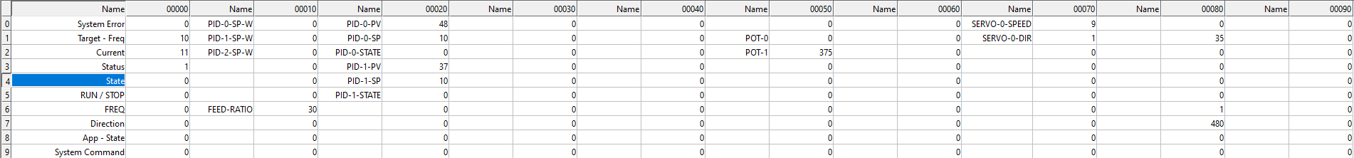
To monitor and control the system, please open printhead-poll.mbp with MbPoll_v9.4.0.exe
Simulate Modbus for Development
- Please use MbSlave_v7.3.0.exe to start a Modbus-RTU master on TCP. You can use the ModbusPoll app to verify your code.