Subsections of Lydia - Printhead Documentation
Installation
Omron MX2
- Please refer to the OmronMX2 - Modbus setup guide../vendor/omron/P641-E1-01_EGuide_CJ_Mod485_OMRON_3G3MX2-V1.pdf(Section 7.2.2)
In case the terminal labels mismatch the documentation, please use SN for (A-) and SP for (B+)
1.1 Set basic parameters
- Max. Frequency, depending on gearbox, A004 = 75Hz
- Acceleration time, F02 = 2secs
- Deceleration time, F03 = 2secs
- Output current on AM terminal (connect L to circuit GND!) as 10V : C28=01
- Enable Brake - A051 = 01 (../vendor/omron/I570-E2-02B.pdf : Page 105)
- The firmware expects the VFD at Slave-Address 1 !
Additionally, please check the user manual../vendor/omron/I570-E2-02B.pdf)
2.1 Modbus settings - Page 297
- Parity : None -
C74= 00 - Speed : 9600 -
C71= 5 - Slave Id : 1 -
C72= 1
2.2 Control settings
- Frequency selection -
A001: 03 (Modbus) - Command selection -
A002: 03 (Modbus)
Please restart the inverter after changing those settings!
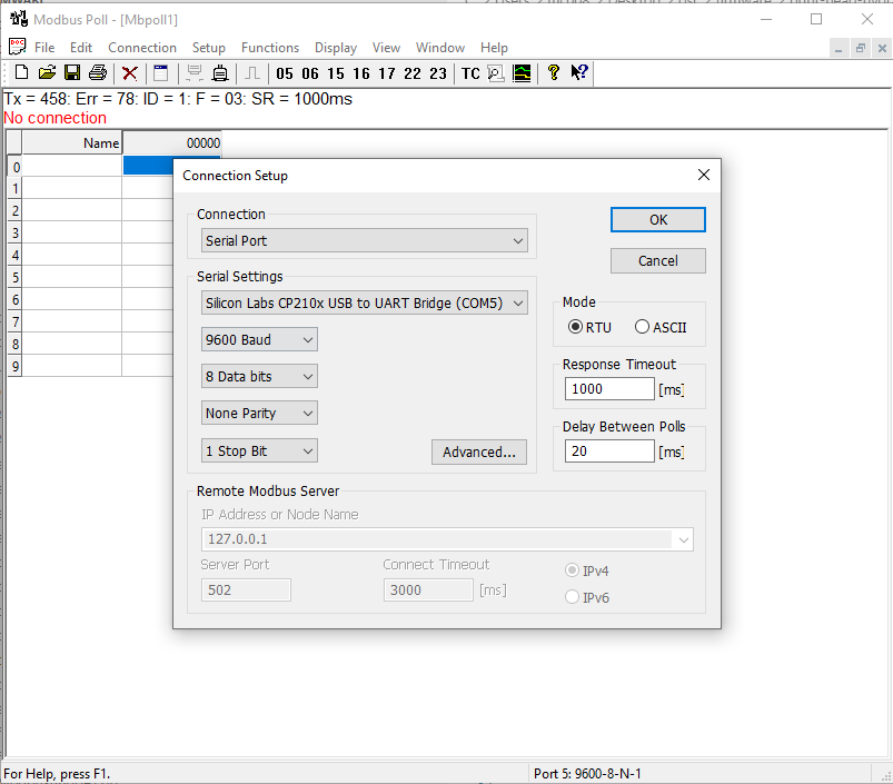
2.3 Test settings, using serial Modbus adapter CP2102 and Modbus poll (see ./tools/MbPoll_v9.4.0_cracked.exe)
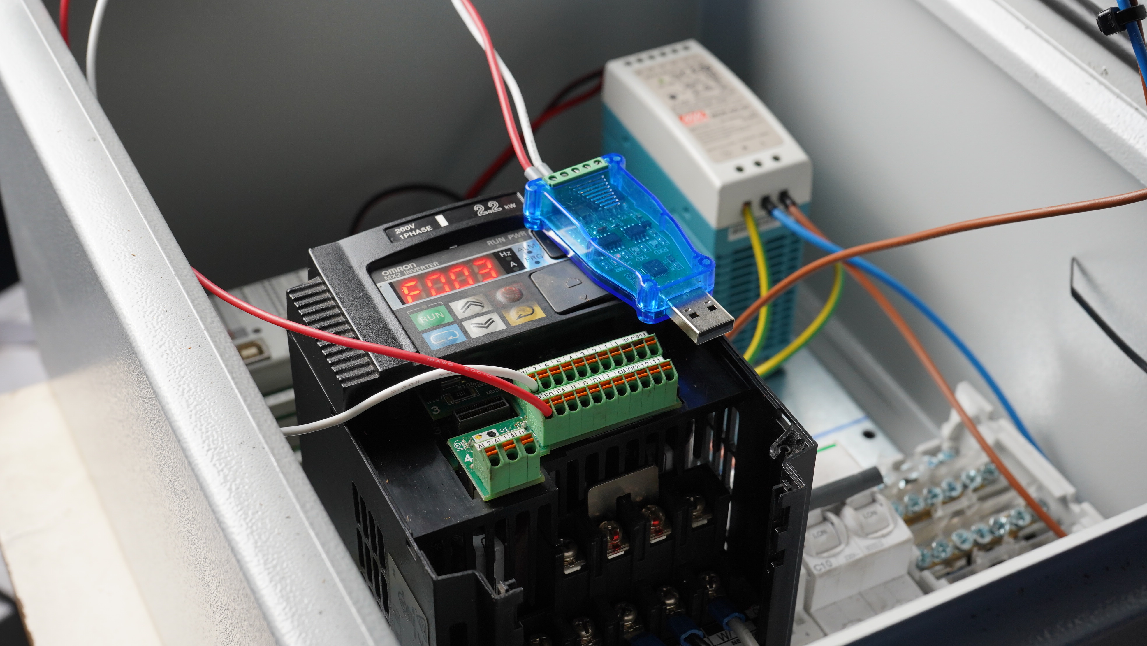
2.3.1 Wire the CP2102 USB adapter

2.3.2 Connect

2.3.3 Function - Write Coil
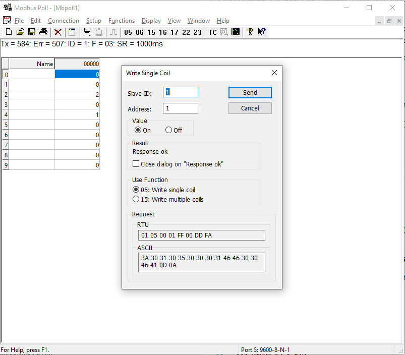
The ‘Run’ LED shoud now be on.
Omron E5 - PID
TCP interface
To set the target temperature to 100 Degc on PID1, the complete message for Modbus TCP would be
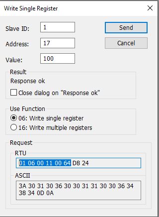
01 06 00 11 00 64 D8 24
01: slave id06: Modbus verb / function code, in this case WRITE HOLDING REGISTER11: address (17)00 64: value (100), 2 bytesD8 24: CRC, 2 bytes. Since it’s TCP, this isn’t evaluated and can be ignored on the Controllino - PlasticHub firmware (see ‘./firmware/Mudbus.cpp’](./firmware/Mudbus.cpp)).
In order to fake a Modbus message, all we need is 01 06 00 11 00 64 but we also have to prefix it with the TCP overhead (d2 8d 00 00 00 06)
|—- TCP Overhead—– | ——– Modbus —- |
d2 8d 00 00 00 06 | 01 06 00 11 00 64
In example, we can send this via Hercules :
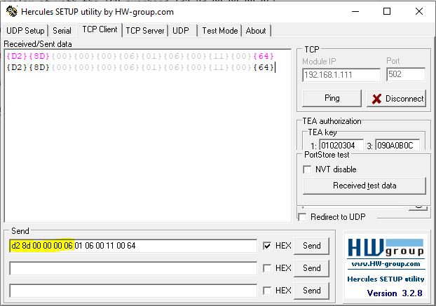
The TCP overhead (d2 8d 00 00 00 06) is created as follow:
d2 8d: Transaction identifier, 2 bytes00 00: Protocol identifier, 2 bytes00 06: Length of the message, 2 bytes
Clearpath - Teknic Servo
-> White (Input A+) -> DIR -> (MB_STEPPER_DIR_0 -> CONTROLLINO_D18)
-> Black (Input B+) -> PULSE -> (MB_STEPPER_PULSE_0 -> CONTROLLINO_D17)
-> Blue (Enable +)  -> 24V
-> YELLOW (Input B-) -> GND
-> Brown (Input A-) -> GND
-> Orrange (Enable B-) -> GND

### Omron - Optional

- [Brake Resistor](https://www.farnell.com/datasheets/2923188.pdf)Subsections of Installation
Omron Setup
Modbus
Modbus - Documentation
Common
The controller exposes a Modbus ‘Master’ at the specified TCP interface on port 502.
There are dedicated registers for the VFD, PIDs and internal values.
System Registers
| Name | Component ID | Address | RW | Function Code | Value | Register Description |
|---|---|---|---|---|---|---|
| System | 1 | 9 | -W | 0x6 | 1 | Print Modbus Queue |
| System | 1 | 9 | -W | 0x6 | 2 | Print Component Modbus Registers |
| System | 1 | 100 | -W | 0x6 | 1 | Reset Controller |
| System | 1 | 19 | -W | 0x6 | 1 | Print PID controller states |
Remarks
- Implementation for these calls : short ModbusBridge::loop() ./ModbusBridge.cpp
- It requires a USB cable connected, with 19200 bauds, 8 bits, no parity and 1 stop bit. You can use Arduino’s ‘Serial Monitor’ to see the output.
VFD Registers
The VFD (Omron - MX2) is being polled and controlled via RS485 at a defined Modbus slave address (Default 1). See more about the setup here.
| Name | Component ID | Address | RW | Function Code | Value | Register Description |
|---|---|---|---|---|---|---|
| VFD | 200 | 5 | -W | 0x6 | 1 | Set VFD in RUN mode |
| VFD | 200 | 5 | -W | 0x6 | 2 | Set VFD in STOP mode |
| VFD | 200 | 5 | -W | 0x6 | 3 | Set VFD in RETRACT mode (stop and retract) |
| VFD | 200 | 6 | -W | 0x6 | 0-100 | VFD Target Frequency |
| VFD | 200 | 2 | -R | 0x6 | 0-100 | VFD Current Monitor |
| VFD | 200 | 3 | -R | 0x6 | - | VFD Status OMRON_STATUS_STOPPED=2 OMRON_STATUS_RUNNING=0 |
| VFD | 200 | 4 | -R | 0x6 | - | VFD State OMRON_STATE_ACCELERATING=4OMRON_STATE_DECELERATING=2 OMRON_STATE_RUNNING=3 OMRON_STATE_STOPPED=1 OMRON_STATE_ERROR=8 |
PID Registers
The PID controllers (Omron - EDC5) are being polled and controlled via RS485 at a defined Modbus slave address, starting by default from 4.
| Name | Component ID | Address | RW | Function Code | Value | Register Description |
|---|---|---|---|---|---|---|
| PID | 100 | 20 | R- | 0x6 | 0-Maximum Temperature (PV) |
PID-0 Temperature |
| PID | 100 | 21 | R- | 0x6 | 0-Maximum Temperature / Set Point | PID-0 Set Point (SP) |
| PID | 100 | 22 | R- | 0x6 | Status | PID-0-Status / Default State : ‘Is Heating’ |
| PID | 100 | 23 | R- | 0x6 | 0-Maximum Temperature (PV) |
PID-1 Temperature |
| PID | 100 | 24 | R- | 0x6 | 0-Maximum Temperature / Set Point | PID-1 Set Point (SP) |
| PID | 100 | 25 | R- | 0x6 | Status | PID-1-Status / Default State : ‘Is Heating’ |
Auxillary Registers (Sensors / Switches)
| Name | ID | Address | RW | Function Code | Number Addresses | Register Description |
|---|---|---|---|---|---|---|
| OmronPID | 100 | 20 | R- | 0x6 | 6 | |
| MB_Relay | 300 | 41 | RW | 1 | 1 | |
| MB_Relay | 301 | 42 | RW | 1 | 1 | |
| POT | 400 | 51 | R- | 3 | 1 | |
| POT | 401 | 52 | R- | 3 | 1 | |
| Pos3Analog | 501 | 61 | R- | 3 | 1 | - Read Position : Address=61(3D) -> [Up:1 Middle:0 Down:2] |
| Pos3Analog | 502 | 62 | R- | 3 | 1 | - Read Position : Address=62(3E) -> [Up:1 Middle:0 Down:2] |
| VFD | 200 | 5 | – | 3 | 1 | |
| Stepper | 601 | 70 | RW | -1 | 4 | |
| MotorLoad | 210 | 2 | R- | 3 | 1 | |
| Status - LED | 701 | 84 | RW | 3 | 1 | |
| Status - LED | 702 | 85 | RW | 3 | 1 |
Stepper
| Name | ID | Address | RW | Function Code | Value | Register Description |
|---|---|---|---|---|---|---|
| Stepper-0 | 601 | 70 | RW | 0x6 | 0-5000 | Stepper-Speed |
| Stepper-0 | 601 | 71 | RW | 0x6 | 0-1 | Stepper-Direction |
| Stepper-0 | 601 | 72 | R- | 0x6 | - | Stepper-Status |
| Stepper-0 | 601 | 72 | – | 0x6 | - | Stepper-User |
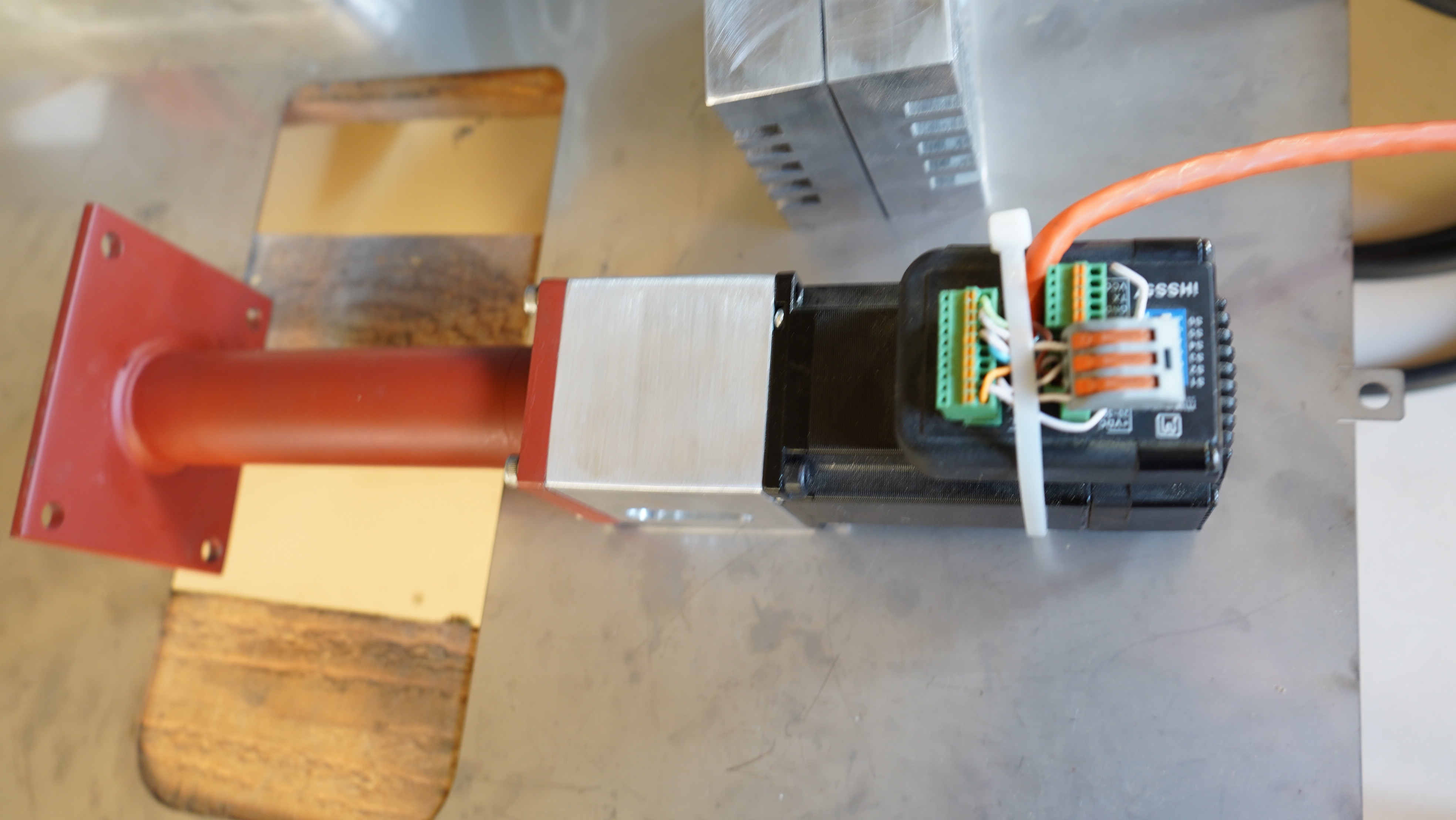
Feed - Servo
| Name | ID | Address | RW | Function Code | Value | Register Description |
|---|---|---|---|---|---|---|
| Feed - VFD - Ratio | 601 | 16 | -W | 0x6 | 0-100 | Stepper-Speed |
The servo is turned on automatically as soon the VFD starts running.
Tools
To monitor and control the system, please open printhead-poll.mbp with MbPoll_v9.4.0.exe
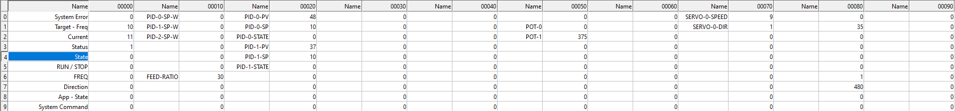
Simulate Modbus for Development
- Please use MbSlave_v7.3.0.exe to start a Modbus-RTU master on TCP. You can use the ModbusPoll app to verify your code.
References
Subsections of Modbus
Modbus - VFD Control
VFD
Start & Stop
Starts or stops the VFD, be aware that a target frequency has to be set as well
- Address : 5
- Function : 6 (WRITE_REGISTER)
- Values :
- On : 1
- Off : 2
TCP Sequence for Start
d2 8d 00 00 00 06 01 06 00 05 00 01
                   +  +  +    +
                   |  |  |    |
                   |  |  |    +----> Value (2 bytes) = 00 01
                   |  |  |
                   |  |  +----> Address (2 bytes) = 05 or 0x0005
                   |  |
                   |  +--> Function Code (Always 6)
                   |
                   +--> Slave - ID (Always 1)
TCP Sequence for Stop
d2 8d 00 00 00 06 01 06 00 05 00 02
                   +  +  +    +
                   |  |  |    |
                   |  |  |    +----> Value (2 bytes) = 00 02
                   |  |  |
                   |  |  +----> Address (2 bytes) = 05 or 0x0005
                   |  |
                   |  +--> Function Code (Always 6)
                   |
                   +--> Slave - ID (Always 1)
Frequency
Sets the target frequency
- Address : 6
- Function : 6 (WRITE_REGISTER)
- Values : 1 - 50
TCP Sequence for setting target frequency to 50 Hz
Remark : Please respect the max. main frequency setting on the inverter (settings)
d2 8d 00 00 00 06 01 06 00 05 00 32
                   +  +  +    +
                   |  |  |    |
                   |  |  |    +----> Value (2 bytes) = 00 32 (for 50Hz)
                   |  |  |
                   |  |  +----> Address (2 bytes) = 06 or 0x0006
                   |  |
                   |  +--> Function Code (Always 6)
                   |
                   +--> Slave - ID (Always 1)
Direction
Sets the rotation
- Address : 7
- Function : 6 (WRITE_REGISTER)
- Values :
- Forward : 1
- Reverse : 2
- Stop : 3
TCP Sequence for setting direction : Forward
d2 8d 00 00 00 06 01 06 00 07 00 01
                   +  +  +    +
                   |  |  |    |
                   |  |  |    +----> Value (2 bytes) = 00 01
                   |  |  |
                   |  |  +----> Address (2 bytes) = 07 or 0x0006
                   |  |
                   |  +--> Function Code (Always 6)
                   |
                   +--> Slave - ID (Always 1)
TCP Sequence for setting direction : Reverse
d2 8d 00 00 00 06 01 06 00 07 00 02
                   +  +  +    +
                   |  |  |    |
                   |  |  |    +----> Value (2 bytes) = 00 02
                   |  |  |
                   |  |  +----> Address (2 bytes) = 07 or 0x0006
                   |  |
                   |  +--> Function Code (Always 6)
                   |
+--> Slave - ID (Always 1)Modbus - PID Control
PID Controllers
The PID controller target temperatures can be set as follows:
- PID 1 : Address 10
- PID 2 : Address 11
- PID 3 : Address 12
Set Target temperature on PID 1 to 100Degc
- Address : 10 (
0x10) - Function : 6 (WRITE_REGISTER)
- Values : 0 - Max Temperature (280)
TCP Sequence
d2 8d 00 00 00 06 01 06 00 0A 00 10
                   +  +  +    +
                   |  |  |    |
                   |  |  |    +----> Value (2 bytes) = 00 10 (16 Degc)
                   |  |  |
                   |  |  +----> Address (2 bytes) = 20 or 0x0014
                   |  |
                   |  +--> Function Code (Always 6)
                   |
                   +--> Slave - ID (Always 1)
Set Target temperature on PID 2to 100Degc
- Address : 11 (
0x0B) - Function : 6 (WRITE_REGISTER)
- Values : 0 - Max Temperature (300)
TCP Sequence
d2 8d 00 00 00 06 01 06 00 0B 00 10
                   +  +  +    +
                   |  |  |    |
                   |  |  |    +----> Value (2 bytes) = 00 64 (100 Degc)
                   |  |  |
                   |  |  +----> Address (2 bytes) = 18 or 0x000B
                   |  |
                   |  +--> Function Code (Always 6)
                   |
                   +--> Slave - ID (Always 1)
Set Target temperature on PID 3 to 100Degc
- Address : 12 (
0x0C) - Function : 6 (WRITE_REGISTER)
- Values : 0 - Max Temperature (300)
TCP Sequence
d2 8d 00 00 00 06 01 06 00 0C 00 10
                   +  +  +    +
                   |  |  |    |
                   |  |  |    +----> Value (2 bytes) = 00 10 (16 Degc)
                   |  |  |
                   |  |  +----> Address (2 bytes) = 0C or 0x000C
                   |  |
                   |  +--> Function Code (Always 6)
                   |
                   +--> Slave - ID (Always 1)
Testing with Modbus Poll

Testing with Hercules

Modbus - Errors
Error Codes
The system exposes the current error code as a Modbus register at address 0x00 (FunctionCode:0x3) :
E_VFD_TIMEOUT= 1002E_PID_TIMEOUT= 2002E_FEED_OVERLOAD= 4001E_VFD_OVERLOAD= 1001
System Debug Commands
| Name | Component ID | Address | RW | Function Code | Value | Register Description |
|---|---|---|---|---|---|---|
| System | 1 | 9 | -W | 0x6 | 1 | Print Modbus Queue |
| System | 1 | 9 | -W | 0x6 | 2 | Print Component Modbus Registers |
| System | 1 | 100 | -W | 0x6 | 1 | Reset Controller |
| System | 1 | 19 | -W | 0x6 | 1 | Print PID controller states |
See more details in the PHApp::onError Implementation
Serial Interface
Serial Interface
Interfaces
Serial
All components provide minimal introspection capabilities : info, debug and custom registered methods. Each method can be called via Serial, eg : <<1;2;64;printRegisters:1:0>> to call ‘printRegisters’ for component 1 (main application).
Command construction :
Command Syntax : <<COMPONENT ID ; VERB ; FLAGS ; PAYLOAD>> whereby PAYLOAD consists out of METHOD:ARG-1:ARG-2
ID : Component Id
VERB : Command Type | Default=EC_METHOD (Class Method)
enum ECALLS
{
    // global function
    EC_COMMAND = 1,
    // addon method
    EC_METHOD = 2,
    // external function
    EC_FUNC = 3,
    // user space
    EC_USER = 10

};
FLAGS : Flags being used for the call. Default = 64
    enum MessageFlags
    {
        NEW = 1 << 1,           // set on target when inbound
        // set on target
        PROCESSING = 1 << 2,
        // set on target when inbound
        PROCESSED = 1 << 3,
        // set on host, turn on debugging through the entire processing chain
        DEBUG = 1 << 4,
        RECEIPT = 1 << 5        // set on host, this will return the new state
};PAYLOAD: String, this string depends on the verb, Default = Class::Method(short,short)
Modbus
Firmware
Requirements
Installation / Compile
Remarks
- Install the following Arduino libraries from the zip!
osr-fw-baseAccelStepperArduino_MemoryFreeArduinoLogVector- and
Controllinoas described below
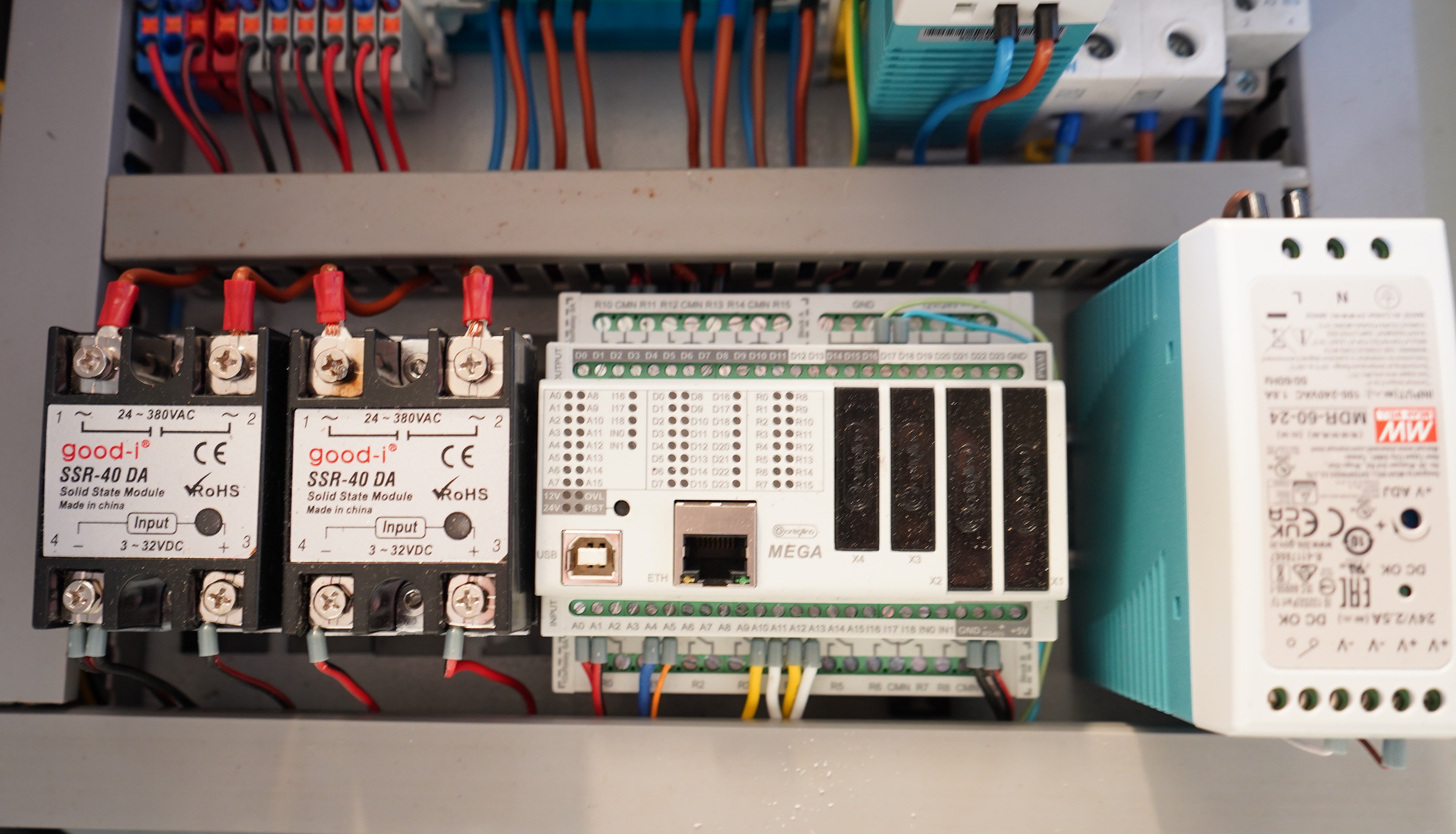
Controllino - Mega
- Arduino - ‘Board’ Manager. See also here, the official documentation
- Navigate to File–>Preferences
- Copy-paste the following link to the Additional Boards Manager URLs:
- For MINI, MAXI & MEGA boards: https://raw.githubusercontent.com/CONTROLLINO-PLC/CONTROLLINO_Library/master/Boards/package_ControllinoHardware_index.json
- For MICRO boards: https://github.com/CONTROLLINO-PLC/controllino_rp2040_firmware/releases/download/global/package_controllino_rp2040_index.json
- Press OK button
- Then navigate to Tools–>Board–>Boards Manager
- In the Boards Manager type CONTROLLINO into the filter text box and search for CONTROLLINO boards (or for CONTROLLINO RP2040 boards in case of MICRO)
- When found, select the latest version and install it. The installation process should be fully automated
- When finished – check in Tools–>Board–> menu that you can see the CONTROLLINO boards there
- Arduino - Controllino Library
- Start Arduino IDE, navigate to Sketch–>Include Library–>Manage Libraries
- In the Library Manager type CONTROLLINO into the filter text box and search for CONTROLLINO library
- When found, select the latest version and install it. The installation process should be fully automated
- When finished – check in Sketch–>Include Library menu that you can see the CONTROLLINO library there
- You can also check if you can see the set of CONTROLLINO examples in File->Examples->CONTROLLINO
Configuration
IP Address
- Change IP Address from default 192.168.1.177 here
Serial Ports
- By default, the firmware is set to 19200, 8 Bits and no parity. That’s due to the limitation of it’s slowest components, Omron-E5DC PID. You can change the settings here ‘Modbus - Commons’
Features
ModBus Related
Debugging
Error Codes
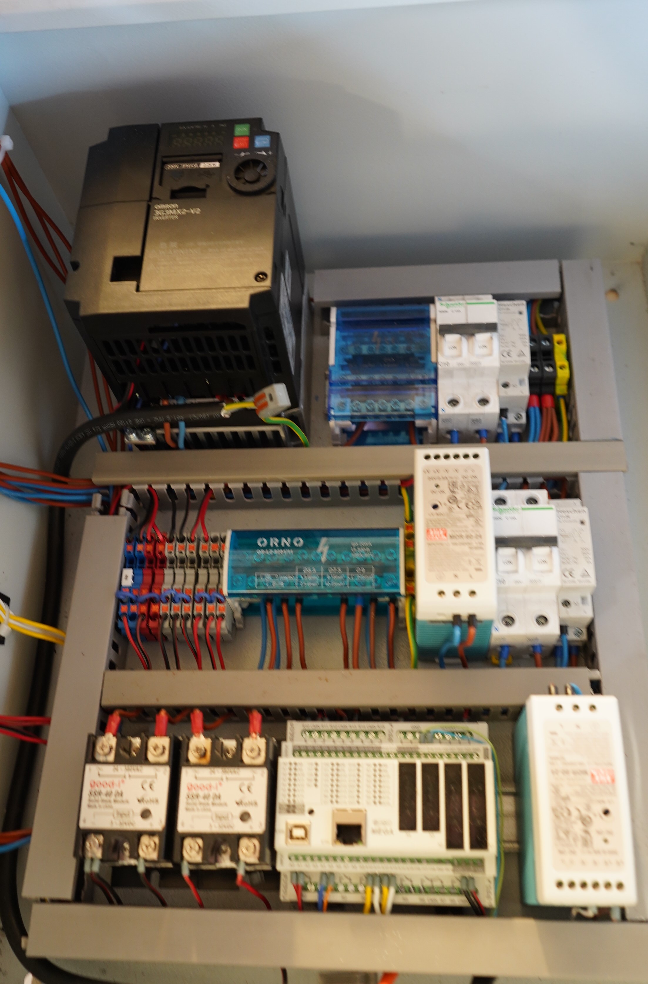
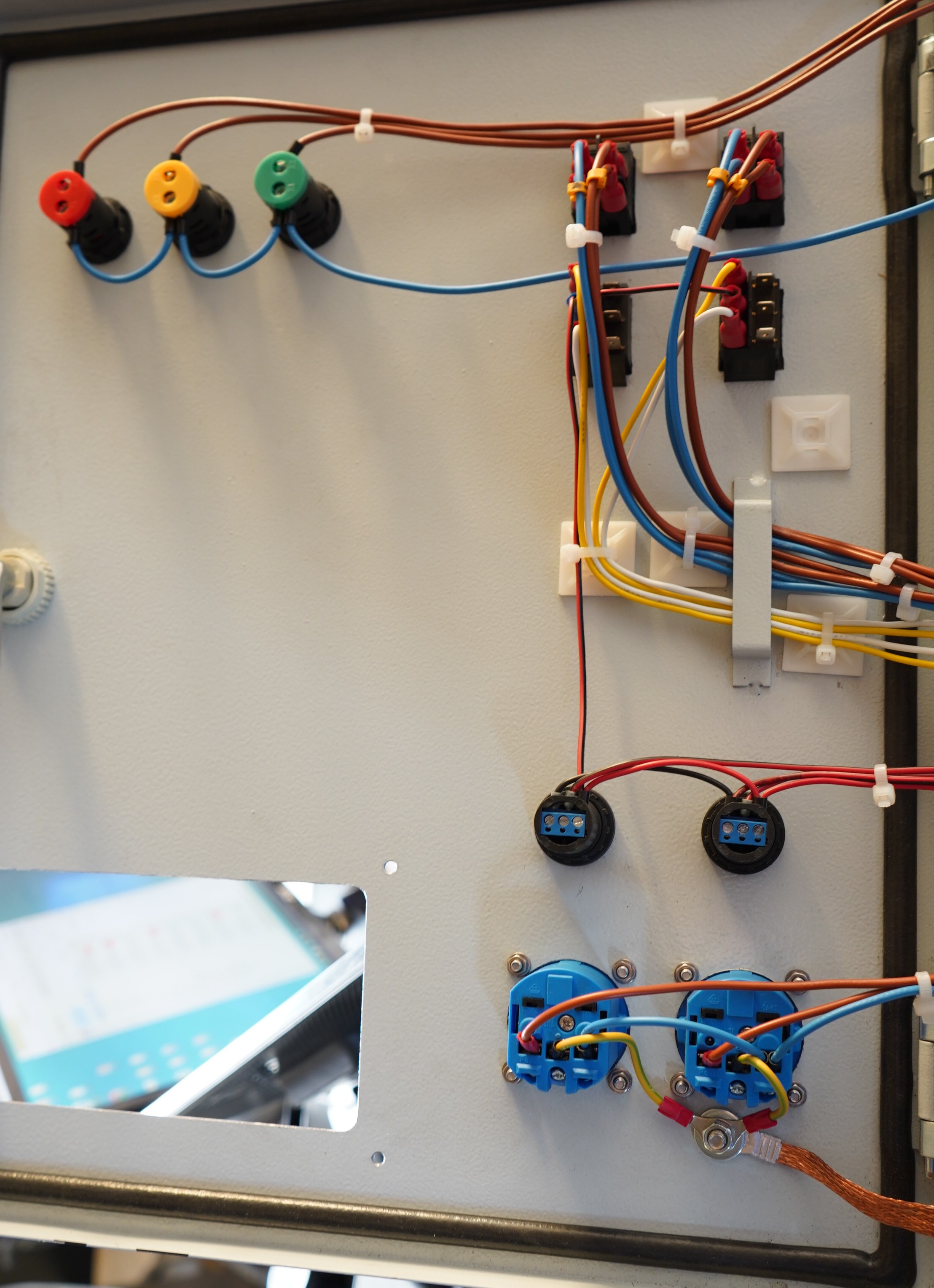
Electrics
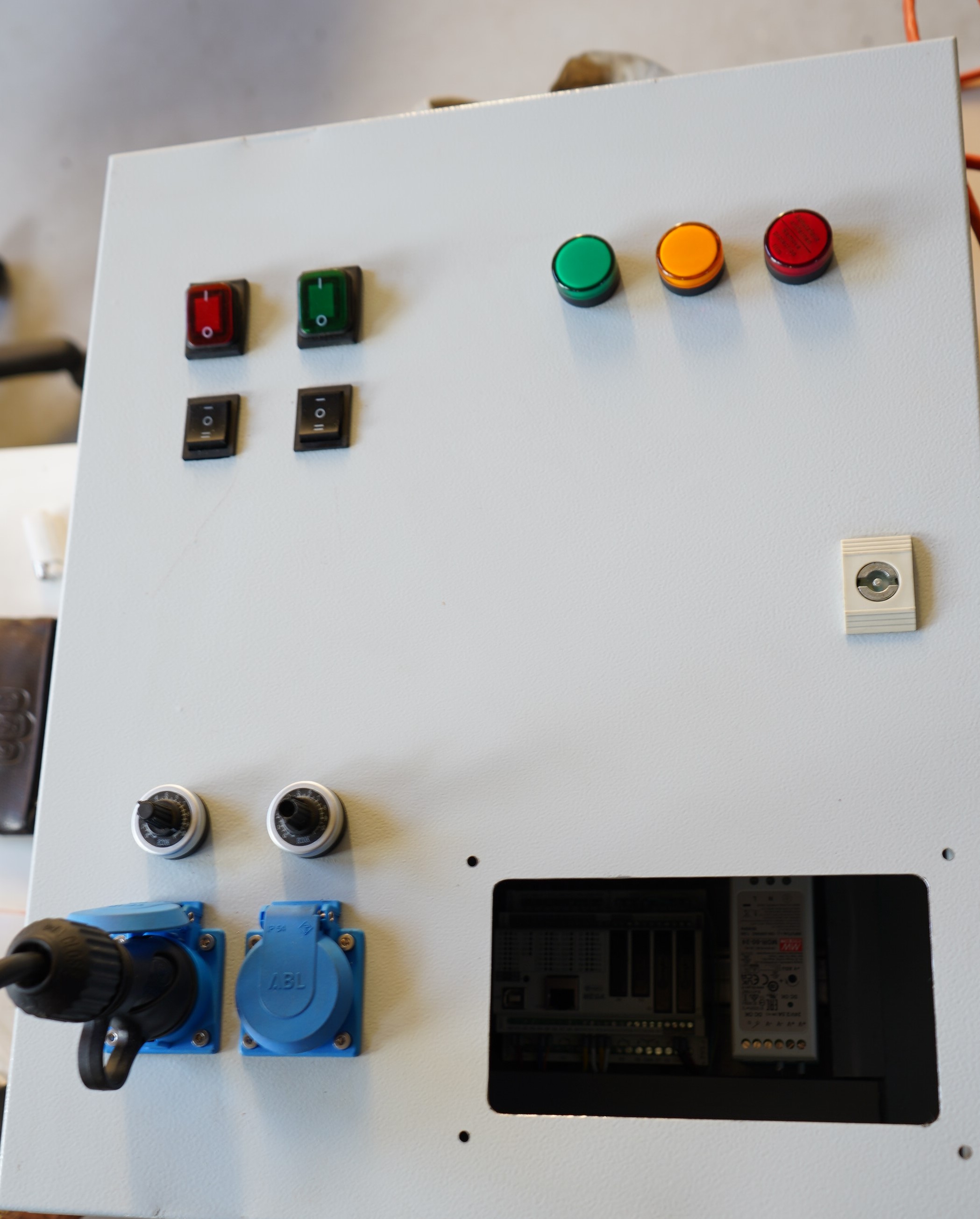
Cabinet

Control Panel


Digital

Feed - Servo
