Installation
Omron MX2
- Please refer to the OmronMX2 - Modbus setup guide../vendor/omron/P641-E1-01_EGuide_CJ_Mod485_OMRON_3G3MX2-V1.pdf(Section 7.2.2)
In case the terminal labels mismatch the documentation, please use SN for (A-) and SP for (B+)
1.1 Set basic parameters
- Max. Frequency, depending on gearbox, A004 = 75Hz
- Acceleration time, F02 = 2secs
- Deceleration time, F03 = 2secs
- Output current on AM terminal (connect L to circuit GND!) as 10V : C28=01
- Enable Brake - A051 = 01 (../vendor/omron/I570-E2-02B.pdf : Page 105)
- The firmware expects the VFD at Slave-Address 1 !
Additionally, please check the user manual../vendor/omron/I570-E2-02B.pdf)
2.1 Modbus settings - Page 297
- Parity : None -
C74= 00 - Speed : 9600 -
C71= 5 - Slave Id : 1 -
C72= 1
2.2 Control settings
- Frequency selection -
A001: 03 (Modbus) - Command selection -
A002: 03 (Modbus)
Please restart the inverter after changing those settings!
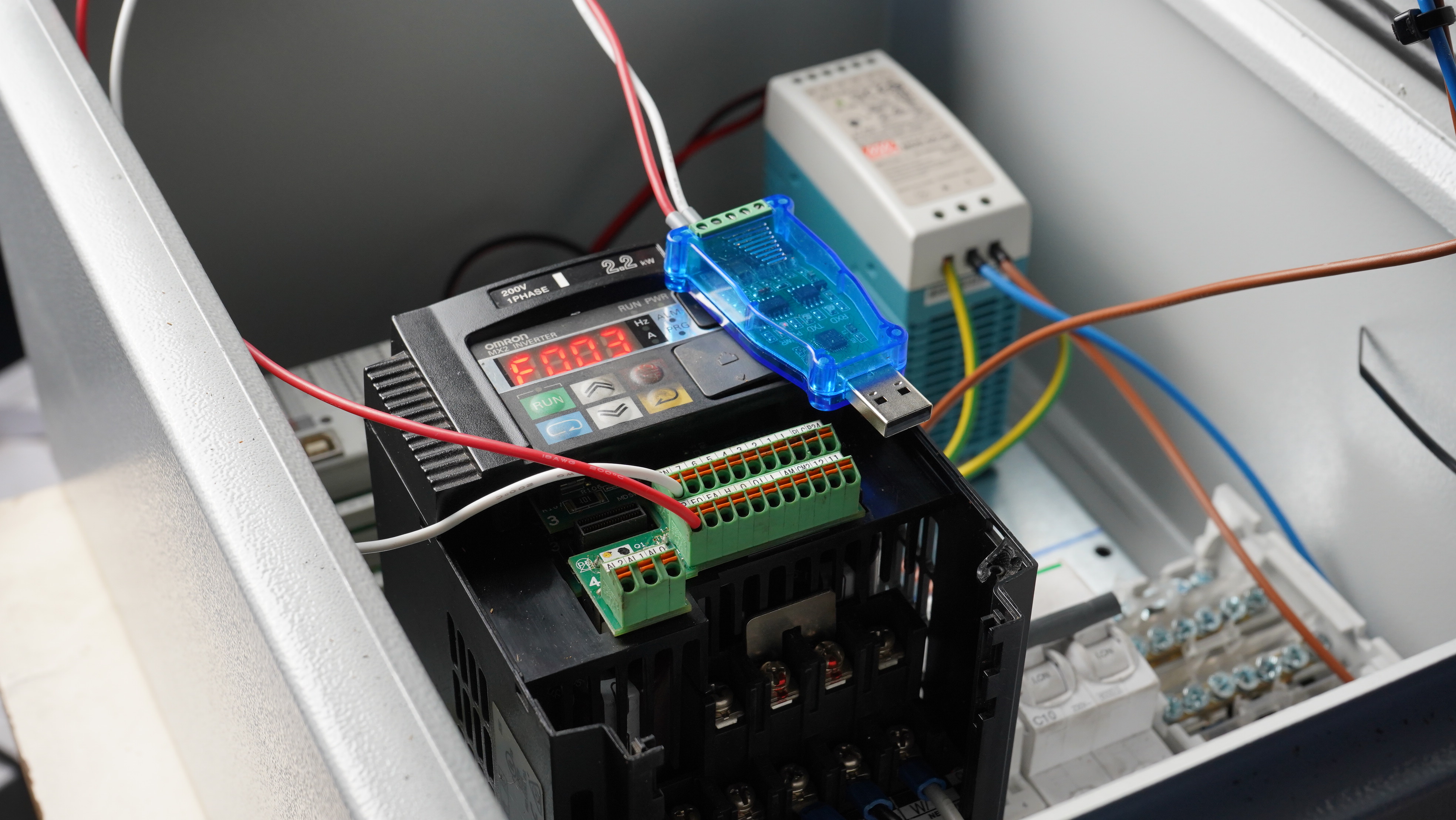
2.3 Test settings, using serial Modbus adapter CP2102 and Modbus poll (see ./tools/MbPoll_v9.4.0_cracked.exe)
2.3.1 Wire the CP2102 USB adapter
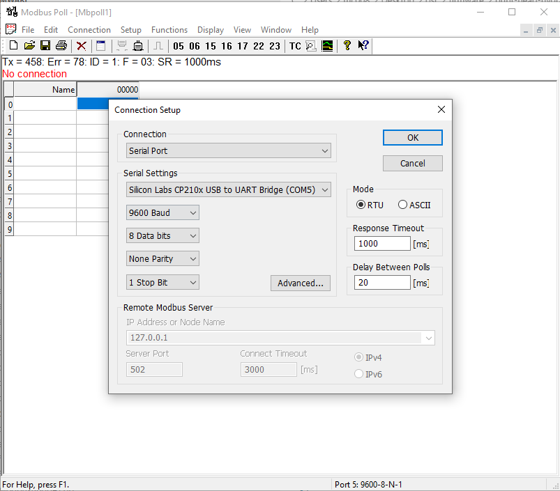
2.3.2 Connect
2.3.3 Function - Write Coil
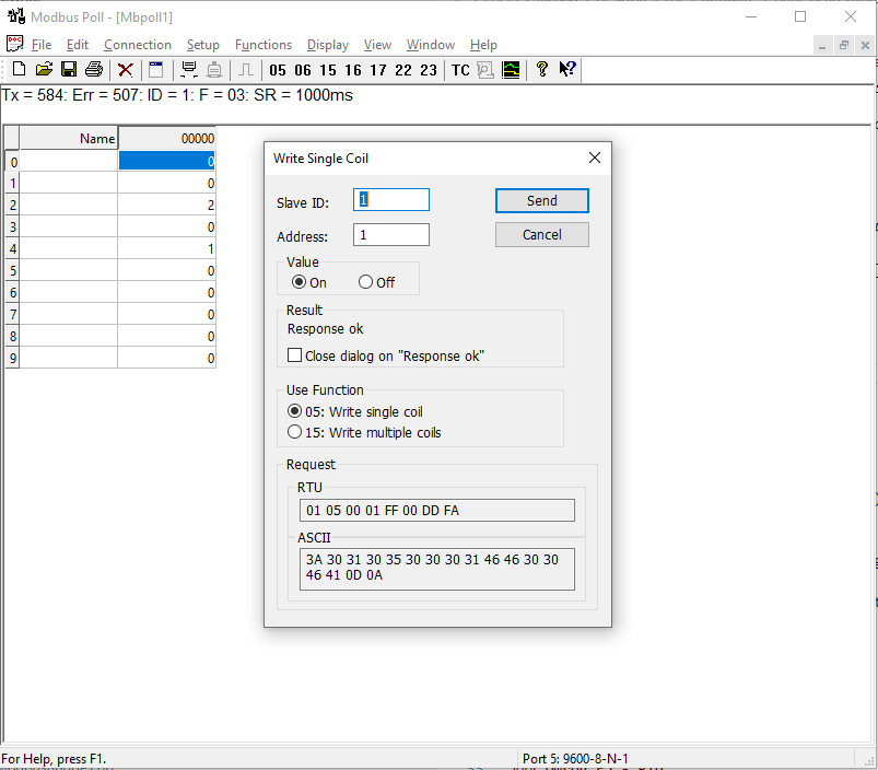
The ‘Run’ LED shoud now be on.
Omron E5 - PID
TCP interface
To set the target temperature to 100 Degc on PID1, the complete message for Modbus TCP would be
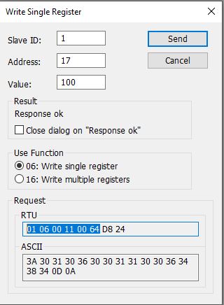
01 06 00 11 00 64 D8 24
01: slave id06: Modbus verb / function code, in this case WRITE HOLDING REGISTER11: address (17)00 64: value (100), 2 bytesD8 24: CRC, 2 bytes. Since it’s TCP, this isn’t evaluated and can be ignored on the Controllino - PlasticHub firmware (see ‘./firmware/Mudbus.cpp’](./firmware/Mudbus.cpp)).
In order to fake a Modbus message, all we need is 01 06 00 11 00 64 but we also have to prefix it with the TCP overhead (d2 8d 00 00 00 06)
|—- TCP Overhead—– | ——– Modbus —- |
d2 8d 00 00 00 06 | 01 06 00 11 00 64
In example, we can send this via Hercules :
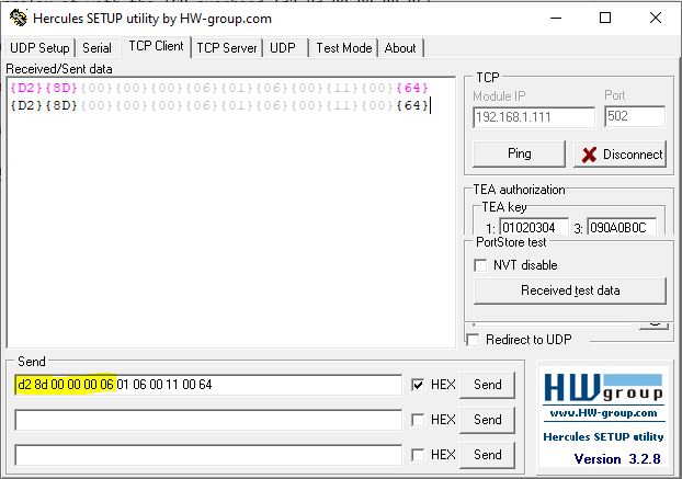
The TCP overhead (d2 8d 00 00 00 06) is created as follow:
d2 8d: Transaction identifier, 2 bytes00 00: Protocol identifier, 2 bytes00 06: Length of the message, 2 bytes
Clearpath - Teknic Servo
-> White (Input A+) -> DIR -> (MB_STEPPER_DIR_0 -> CONTROLLINO_D18)
-> Black (Input B+) -> PULSE -> (MB_STEPPER_PULSE_0 -> CONTROLLINO_D17)
-> Blue (Enable +)  -> 24V
-> YELLOW (Input B-) -> GND
-> Brown (Input A-) -> GND
-> Orrange (Enable B-) -> GND

### Omron - Optional

- [Brake Resistor](https://www.farnell.com/datasheets/2923188.pdf)